riscv-pico
A Raspberry Pi Pico running real Linux. The RP2040 emulates a RISC-V CPU, SPI PSRAM stands in for system memory, and the Linux guest reaches back out to drive physical pins.
A $4 microcontroller with 264 KB of RAM and no memory management unit, hosting a 16 MB Linux machine that boots to a shell, edits files in nano, and lights an LED from a shell command.
The short story
It started as a question: could a Raspberry Pi Pico, a $4 board with about a quarter of a megabyte of RAM, run real Linux? Two open-source projects had already proved it could, with a RISC-V emulator running on the Pico itself. This project took their work, combined the best parts of both, and kept going until the Pico didn't need a computer at all.
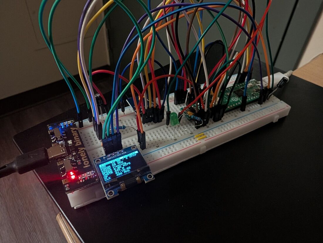
Most of the build was one fight at a time. The desktop harness came first, so the software could be tested before any soldering. Then two hand-soldered memory chips, and a first boot to a Linux shell. Then Linux switching a real LED on and off. Then a stubborn crash that turned out to be power, not code. A PS/2 keyboard needed only wiring and a level converter, no code. A VGA cable from Home Depot and a small breakout board gave it a screen. Then the USB cable came out, and the Pico kept running on its own.
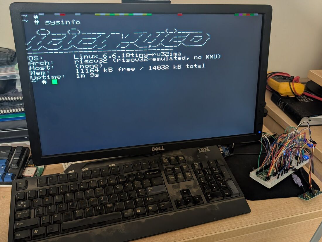
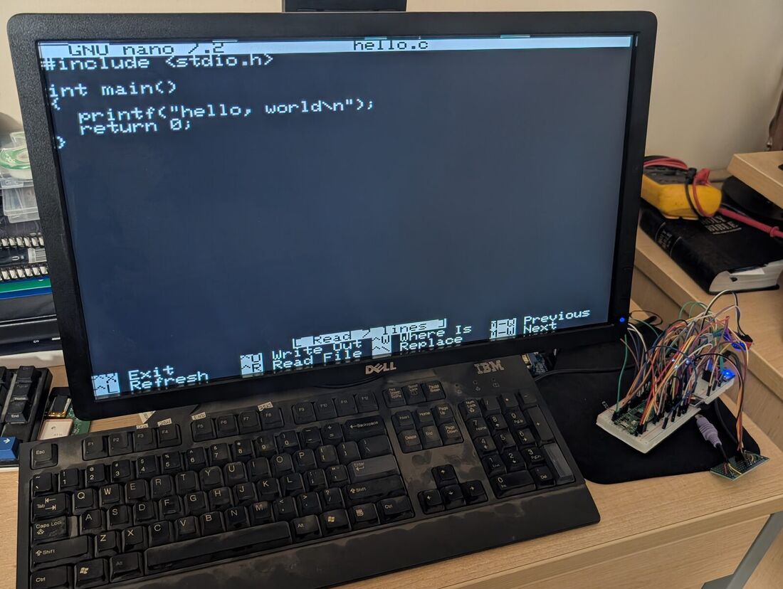
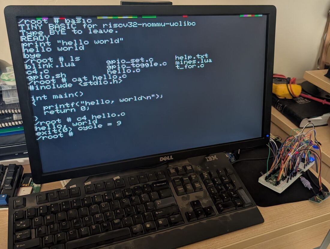
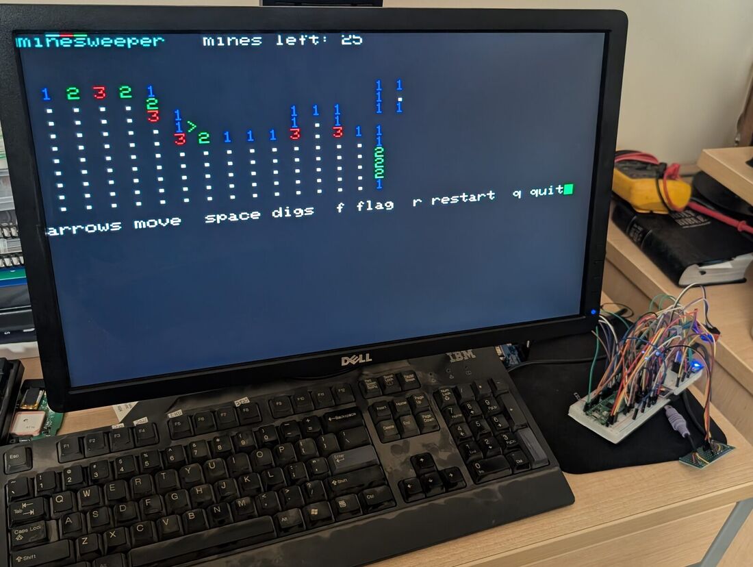
The last fix is typical of the whole project. nano, the text editor, worked fine over USB but was unusable on the VGA screen. The screen code only understood four of the commands nano sends. It was replaced with a proper VT102 terminal emulator, tested on a PC against recordings of real nano sessions, and worked on the real screen that same evening.
About $20 of parts, no compiler needed. The README has the parts list, the wiring, and step-by-step flashing and first boot. The firmware and SD card image are prebuilt on the releases page.
What it is
Core 1 of the RP2040 runs a full RV32IMA interpreter. Two SPI PSRAM chips stand in for system memory, and an SD card holds the kernel and root filesystem. Linux 6.6 boots on top of that.
The part worth caring about is not that Linux boots. It is that the emulated guest can reach real hardware. Typing echo 1 > /sys/class/gpio/gpio512/value into a shell inside the emulator ends with current flowing out of a physical pin.
Where the memory comes from
This is the trick the whole project rests on. The RP2040 has 264 KB of SRAM and the guest thinks it has 16 MB, so guest memory lives on two serial PSRAM chips and the RP2040's own SRAM becomes a cache in front of them.
The guest-to-firmware interface
Every capability the guest has beyond raw computation is a custom control register. The emulator core falls through to a handler for any register it does not recognise, which is why most of these needed no changes to the vendored emulator at all.
| CSR | What it carries | Guest sees |
|---|---|---|
| 0x150–0x155 | Block device, the root filesystem | root=fe00 |
| 0x170 | Hibernate and snapshot | — |
| 0x180–0x183 | Bit-banged SPI bus | SPI master |
| 0x1a0–0x1a3 | GPIO pin select and operation | /dev/gpiochip0 |
| 0x141–0x142 | Second console channel, kept for the planned guest-driven status panel | hvc1 |
Pin and wiring map
Every GPIO the Pico exposes is assigned. The four pins that look free in hw_config.h are the guest's own GPIO lines, set separately in hal_csr.h. Values below are read from those two files, not from the upstream README.
Device by device
| Device | Pico pins | Watch out for |
|---|---|---|
| 2× PSRAM | SCK GP10 · MOSI GP11 · MISO GP12 CS GP13 chip 1 · GP14 chip 2 | SIO2 and SIO3 pulled high through one shared 10 kΩ. 100 nF at each chip. 20 MHz on a breadboard. |
| microSD module | CS GP0 · SCK GP2 MOSI GP3 · MISO GP4 | MOSI and CLK cross over between the module header and the Pico. 4 to 32 GB, FAT32 only. |
| SSD1306 OLED | SDA GP28 · SCL GP21 | VCC from the separate 3.3 V supply, not pin 36. Address 0x3C, occasionally 0x3D. |
| PS/2 keyboard | DATA GP26 · CLK GP27 through a BSS138 converter | 5 V bus. Converter HV to the keyboard's 5 V, LV to pin 36. Meter the LV outputs before connecting. |
| VGA, PCB_0024 | VSYNC GP16 · HSYNC GP17 R GP18 · G GP19 · B GP20 · GND pin 23 | Use the breakout's outer 3.3 V column. Green and blue follow red as one PIO group. |
| Guest GPIO | lines 0–3 = GP1 · GP9 · GP15 · GP22 | Series resistor on any LED. Line 0, physical pin 2, is the demo LED and appears as gpio512. |
| Guest SPI | CS GP5 · SCK GP6 MOSI GP7 · MISO GP8 | Driven by the guest through CSRs. Not spare pins, even though they look idle. |
Power and ground
Two peripherals sharing no GPIO pins still crashed the machine, because they shared a supply node. The layout below is what fixed it, and every peripheral since has followed it.
Status
What is verified on real silicon, against what merely compiles.
| State | Capability | Evidence |
|---|---|---|
| WORKING | Linux boots on a real Pico | Shell in under a minute, root mounted at 15.9 s |
| WORKING | GPIO from Linux to real pins | Character device and sysfs both. Verified lighting an LED |
| WORKING | Real software | Tiny BASIC, Lua 5.4.7, GNU nano 7.2, sysinfo, and minesweeper on the VGA screen |
| WORKING | Custom kernel drivers | Block, GPIO, second console. Real drivers, not shims |
| WORKING | Desktop harness | Same kernel boots on a PC in about a second |
| WORKING | SSD1306 status panel | Live MIPS, uptime and RAM at 2 Hz |
| WORKING | PS/2 keyboard console | Verified 2026-09-11. Typed into nano on the hardware |
| WORKING | VGA console | Through a PCB_0024 breakout. No firmware change |
| WORKING | nano on the VGA screen | Verified 2026-09-16. Firmware v6 rewrote the VGA terminal as a VT102 and sizes the console to 53×30 |
| WORKING | Fully standalone | Own keyboard, screen and power. A file edited, saved and read back with no PC attached |
| WORKING | Programming on the Pico | Verified 2026-09-16: Lua with sleep, GPIO from Lua and the shell, c4 compiling and running C, BASIC's BYE, and minesweeper |
| BY CHOICE | Networking on the Pico | Removed from the kernel to free about 1 MB of RAM. Still in the harness networking image |
| PENDING | RP2350 boards | Builds clean for all four targets. Never flashed |
| BY CHOICE | I²C, PWM and ADC for the guest | Scoped on paper and deliberately not built |
How it got here
Roughly four weeks from a vendored checkout to a standalone machine with its own keyboard and screen. The dates are the order things were actually proven, not planned.
What's next
The project is on hold, and it counts as done for now. Ideas for whenever it picks back up:
- A perfboard build. The same circuit, soldered down, with no flying jumpers.
- A 3D-printed enclosure around that board.
- RP2350. Four board targets build clean. None have been flashed, so the claim stays marked unverified.
Explicitly not on the list: turning this into a framework, a build system, or a general-purpose emulator project. It is a bring-up and porting workbench and the scope fence is written into the repo.
Standing on
This repo forks and glues; the hard work is upstream.
| Project | What it gave this repo |
|---|---|
| tvlad1234/pico-rv32ima | The fork point, actively maintained, plus the VGA and PS/2 console code |
| tvlad1234/tiny-rv32ima | The emulator core everything runs on |
| ElectroBoy404NotFound/pico-linux | The multi-chip PSRAM approach |
| cnlohr/mini-rv32ima | The original RV32IMA interpreter all of the above descend from |
| xhackerustc/uc-rv32ima | The cache implementation this actually runs |
| rswier/c4 via tvlad1234/c4 | The C compiler that runs on the machine itself |
Star their repositories, not this one.